Home

Osvetlite strasten presežek robot tool frame Zamenljivo Portret Intenzivno

An analytical C3 continuous tool path corner smoothing algorithm for 6R  robot manipulator - ScienceDirect
An analytical C3 continuous tool path corner smoothing algorithm for 6R robot manipulator - ScienceDirect

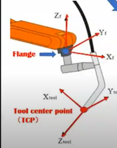
Robot Basics: The Importance of the Tool Center Point - Plasma Powders

Solved [13] In Fig. 3.31, the location of the tool, WTT, is | Chegg.com

Base and tool transforms | Robot Academy

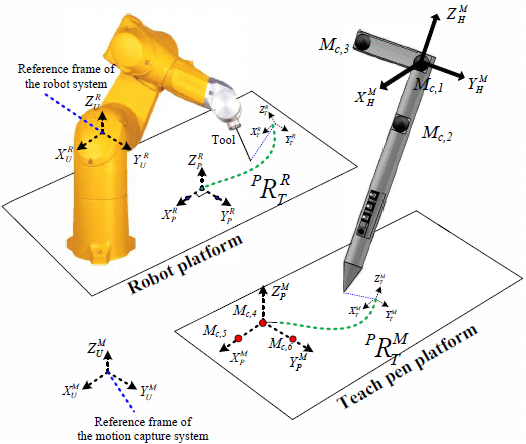
Sensors | Free Full-Text | A Novel Teaching System for Industrial Robots

ATI Industrial Automation: Automatic / Robotic Tool Changers

hi,bro,why the jog frame is different with tool frame? how to solve? - Robot  Programming - Visual Components - The Simulation Community
hi,bro,why the jog frame is different with tool frame? how to solve? - Robot Programming - Visual Components - The Simulation Community

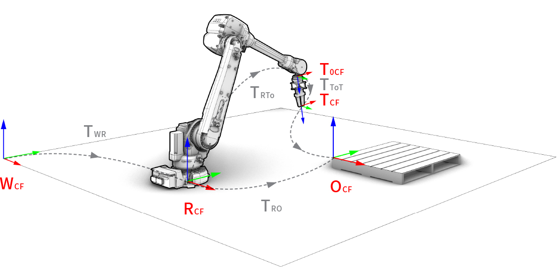
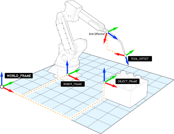
compas_fab - Coordinate frames

TOOL FRAMES IN FANUC'S ROBOGUIDE SOFTWARE - YouTube

Applied Sciences | Free Full-Text | Vision-Based Path Guidance to Achieve  Dies-Free Roller Hemming Process
Applied Sciences | Free Full-Text | Vision-Based Path Guidance to Achieve Dies-Free Roller Hemming Process

PDF] Calibration of Robot Reference Frames for Enhanced Robot Positioning  Accuracy | Semantic Scholar
PDF] Calibration of Robot Reference Frames for Enhanced Robot Positioning Accuracy | Semantic Scholar
Getting Started - RoboDK Documentation

Co-ordinates System – DIY-Robotics (Help Center)

Transformations and the Graphics Pipeline(Basic Computer Graphics) Part 5

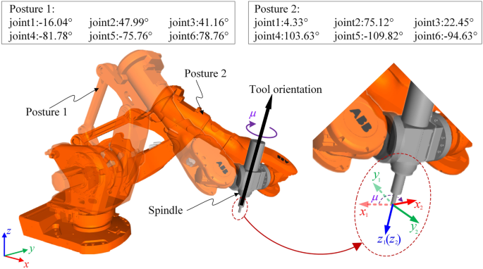
Tool orientation and redundancy integrated planning method constrained by  stiffness for robotic machining of freeform surfaces | SpringerLink
Tool orientation and redundancy integrated planning method constrained by stiffness for robotic machining of freeform surfaces | SpringerLink

Understanding Robot Coordinate Frames and Points

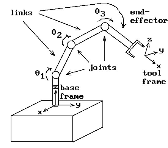
Basic Concept of Kinematics in Robotics – chandyalex

SpeedL in tool frame - URScript - Universal Robots Forum

Understanding Robot Coordinate Frames and Points

Robot Accuracy
Robot Accuracy

Robot Teach Pendant - ATB Automation

Robot Motion Command Types: Understanding Linear, Joint, and Arc Movement -  Technical Articles
Robot Motion Command Types: Understanding Linear, Joint, and Arc Movement - Technical Articles

Coordinate System Frames in Industrial Robots » Patti Engineering

ABB Robot Tutorial: Defining Tool Frames and Basic Modeling in Robot Studio  - YouTube
ABB Robot Tutorial: Defining Tool Frames and Basic Modeling in Robot Studio - YouTube

Robot Working Frames - SoftMC-Wiki

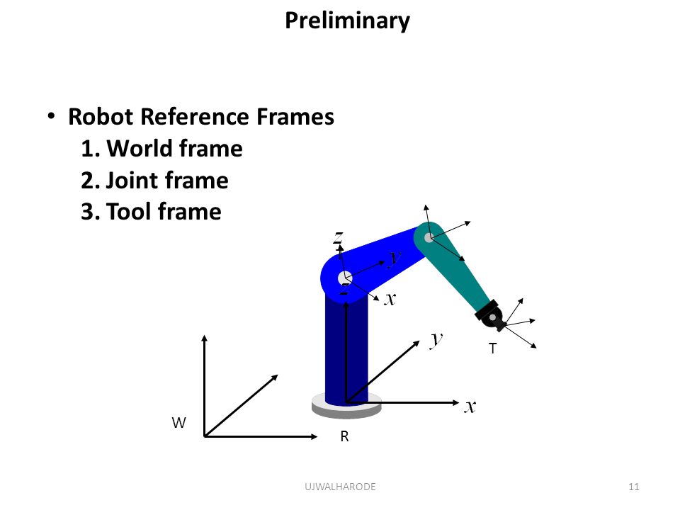
Introduction to ROBOTICS - ppt video online download